
Commodore 64 as a USB Keyboard Mod

Overview
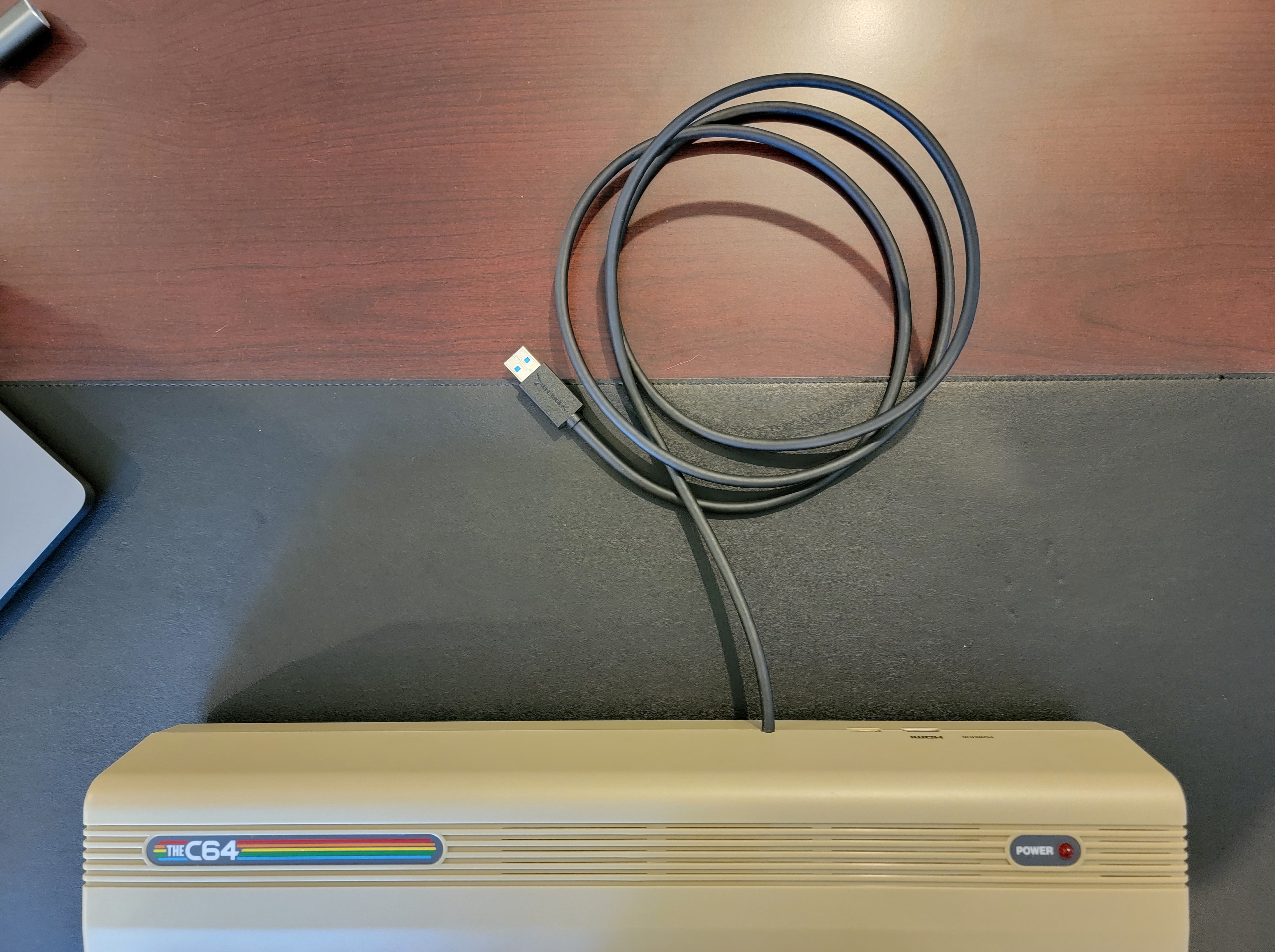
I thought it would be a fun project to make a Commodore 64 Breadbin USB keyboard since I grew up with a Commodore PET and a C64C. I found a Commodore 64 replica called The C64 and learned its keyboard is internally USB and could be rewired as a standalone device. I bought one from Amazon for $129.99.
The C64 Community forum has an informative thread where other users explain how to modify the device, but their procedures require soldering which I typically avoid. So, I created my own solder-free mod that can be reverted easily.
The Mod
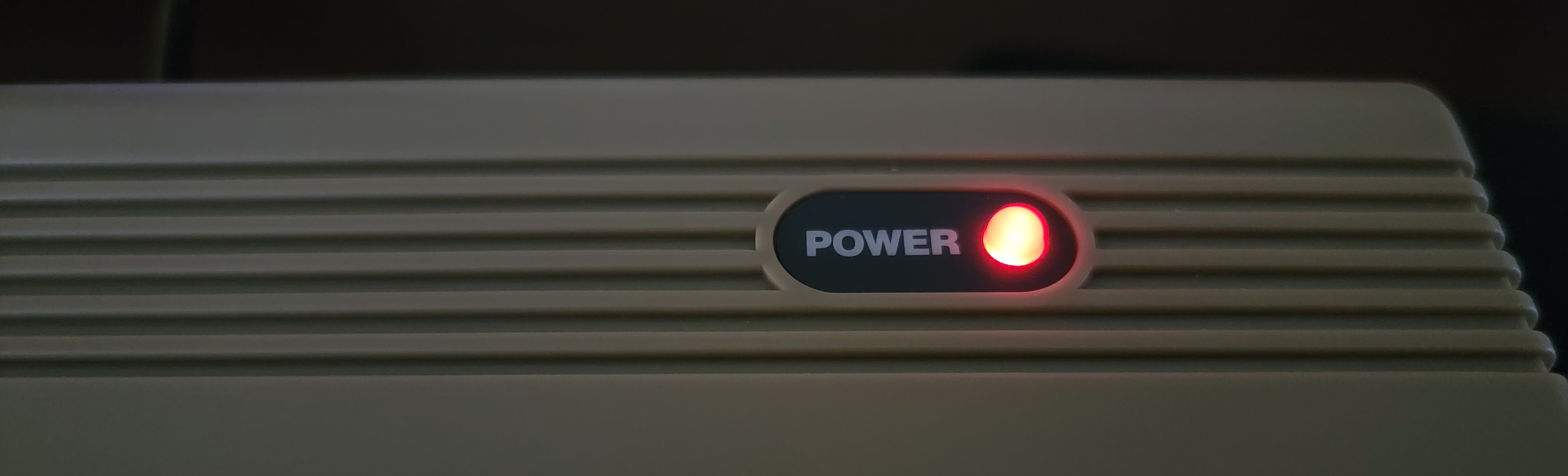
This modification allows you to use the keyboard and the USB hub on the right of The C64 through a single USB cable connected to a host device. The power LED above the keyboard will also light up when you plug in the USB cable.
You will bypass the main board, so the keyboard, hub, and LED cannot be used with the emulator if you power it up.
Parts
You can get away with reusing parts from other projects and reclaiming components from dead machines, but my mod relies on parts sourced from Amazon.
| Item | Quantity | Purchase price (USD) |
| Dupont IDC 5-Pin to USB 2.0 male cable (2-pack) | 2 | $8.99 |
| 2mm straight single row breakaway male pin headers | 1 | $12.29 |
| Assorted 2.54mm and 2mm jumper wires | 1 | $8.69 |
| 6-Foot USB 3.0 extension cable | 1 | $7.99 |
| 4-Port USB 3.0 hub | 1 | $10.99 |
Total: $57.94 (without tax)
Note: You'll need those 2mm to 2.54mm jumper wires because the 5-pin USB header has a 2.54mm pitch while the main board connectors are 2mm.
Procedure
The colors of 2mm to 2.54mm jumper wires in the images below don't match the color of the wires they're connecting.
- Open the case by removing the three screws from the bottom of the case.
- Adapt the keyboard
- Identify the 4-wire cable that connects the keyboard to the main board. This is a standard USB cable with +5V (red), DATA - (white), DATA + (green), and ground (black) wires.
- Disconnect the wire's connector from the main board.
- Break four 2mm pins off the breakaway male pin headers.
- Get four 2mm to 2.54mm jumper wires.
- Insert the block of four 2mm pin headers into the 2mm end of the 2mm to 2.54mm jumper wires.
- Connect the other ends of the four 2mm pin headers into the keyboard cable's connector.
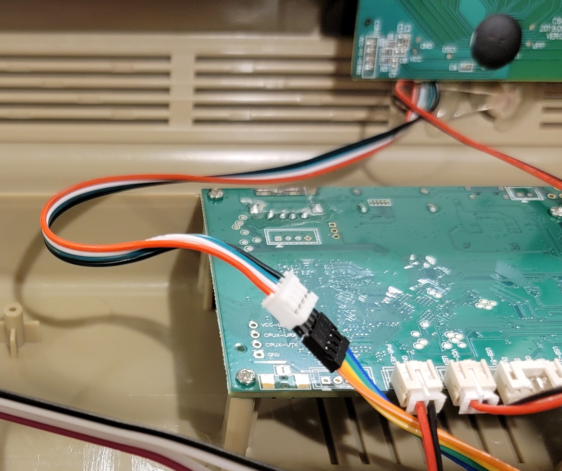
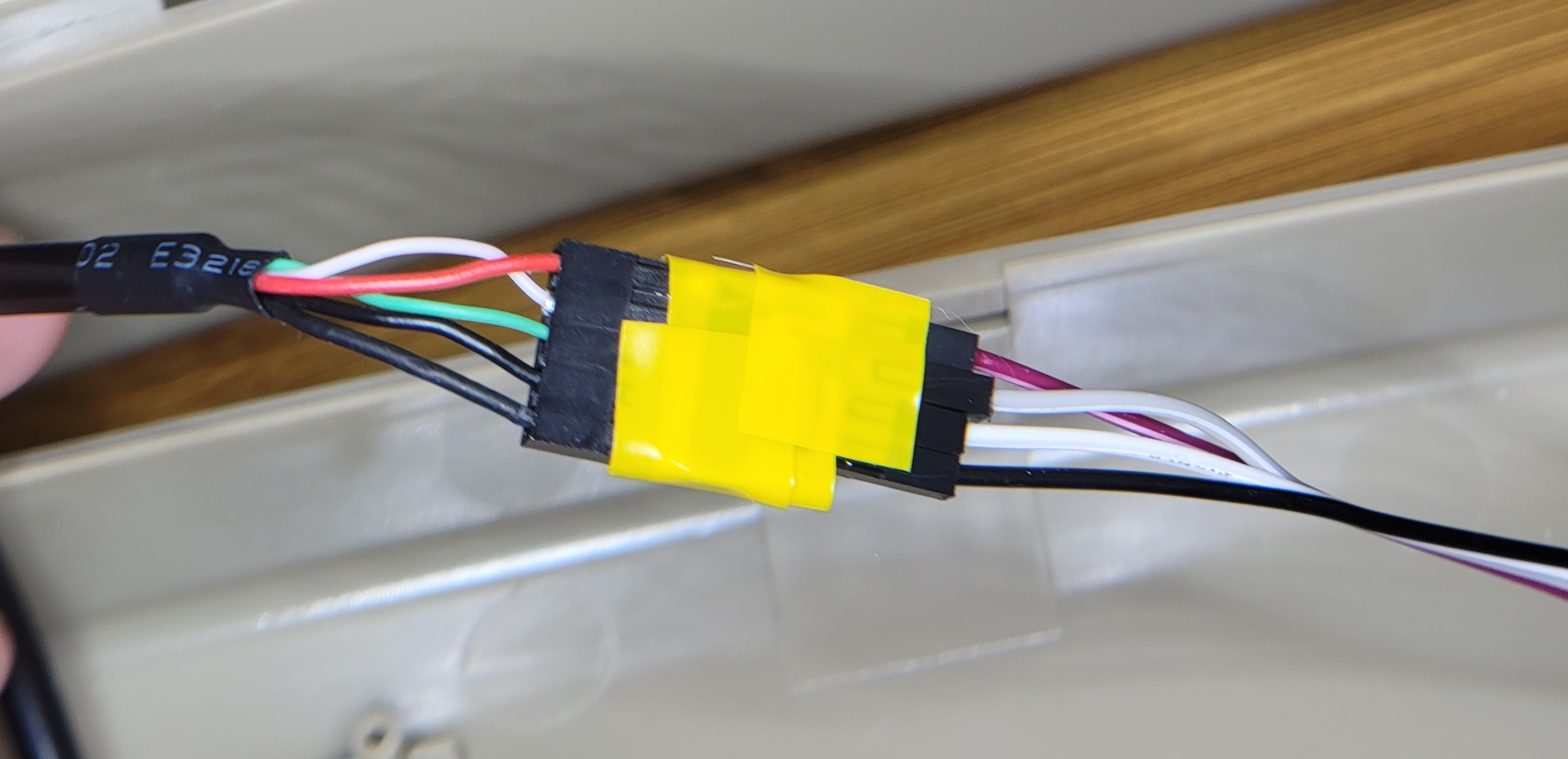
- Connect the 2.54mm ends of the jumper wires to the 5-pin to USB male cable so the red, white, green, and black wires are matched on both ends of the jumper wire. Use the black wire that's next to the green wire. You can ignore the outermost pin (black) which is the shielded ground.
- Plug the USB cable into a device and test that the keyboard works.
- Wrap some electrical tape around the coupled connectors on either end of the jumper wire to secure the connection. This is optional.
- Adapt the LED
- Identify the 2-wire cable that connects the LED to the main board. This cable has a red wire and a black wire. Note: There should be a resistor already soldered to the LED.
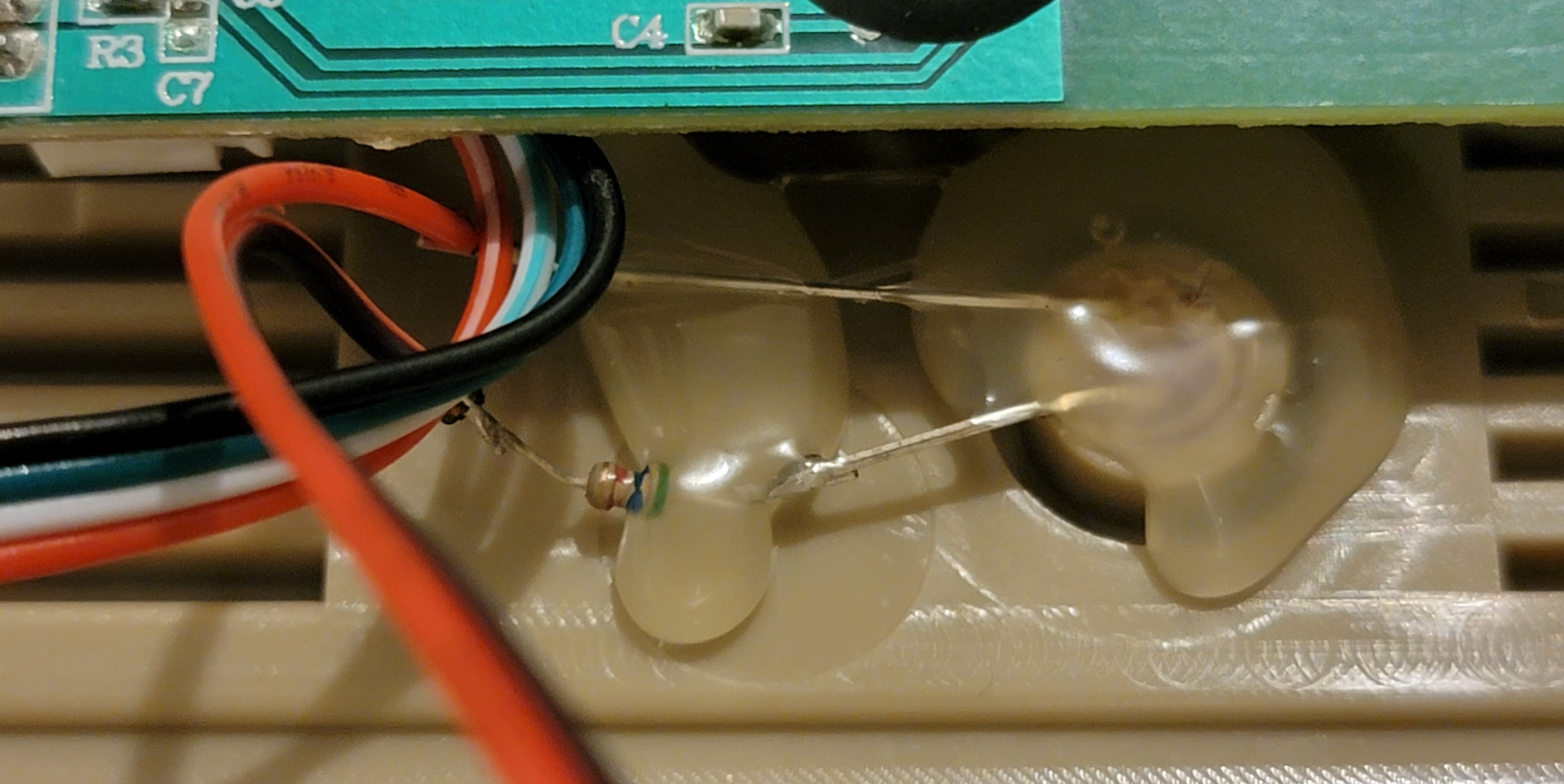
- Disconnect the wire's connector from the main board.
- Break two 2mm pins off the breakaway male pin headers.
- Get two 2mm to 2.54mm jumper wires.
- Insert the block of two 2mm pin headers into the 2mm end of the 2mm to 2.54mm jumper wires.
- Connect the other ends of the two 2mm pin headers into the LED cable's connector.
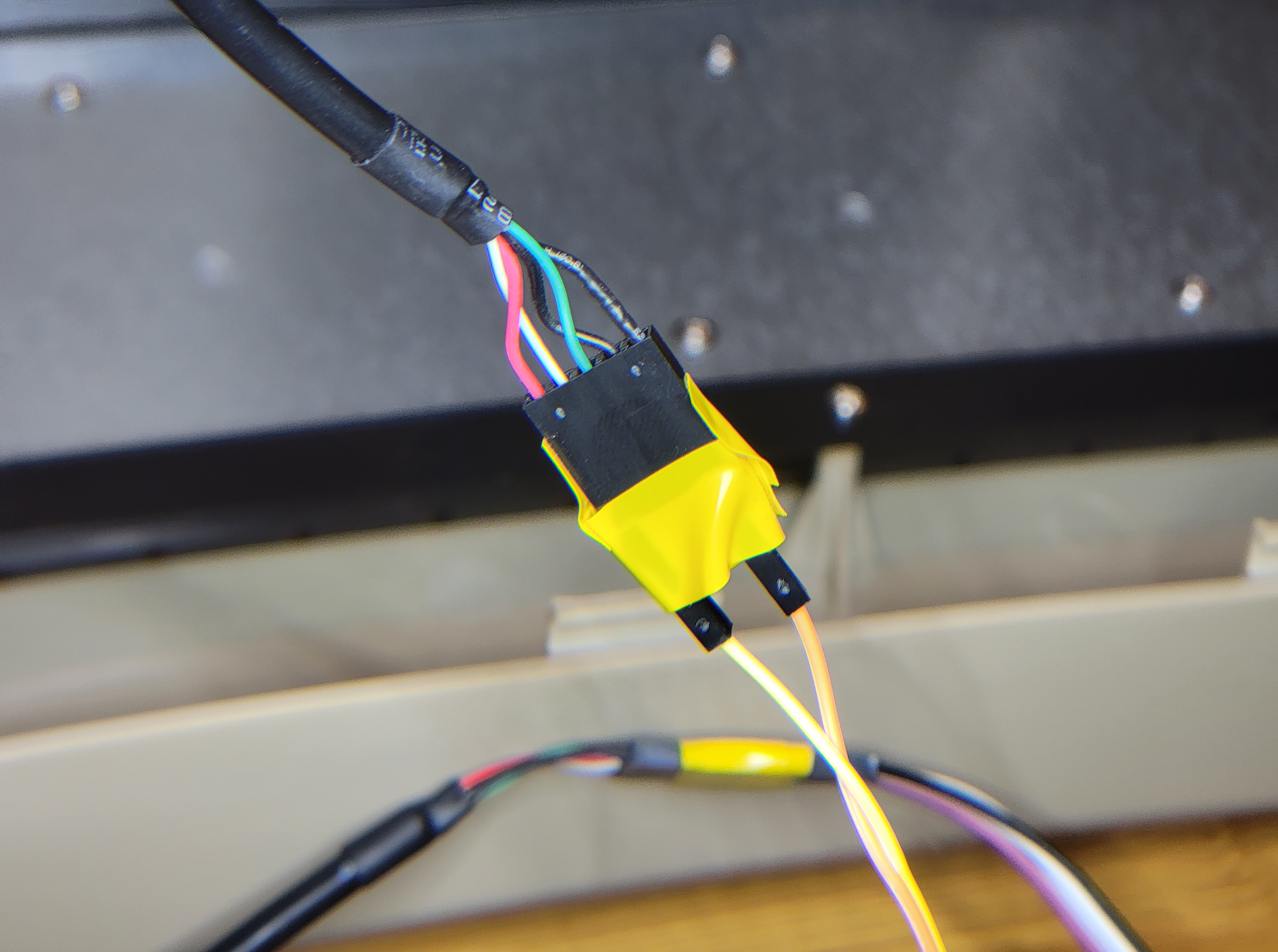
- Connect the 2.54mm ends of the jumper wires to the 5-pin to USB male cable so the red cable is matched to the red cable of the LED connector, and the black ground wire is matched to the black cable of the LED connector. Use the black ground wire that's next to the green cable and not the black shielded ground that's on the end of the header.
- Plug the USB cable into a device and test that the LED light turns on.
- Wrap some electrical tape around the coupled connectors on either end of the jumper wire to secure the connection. This is optional.
- Identify the 2-wire cable that connects the LED to the main board. This cable has a red wire and a black wire. Note: There should be a resistor already soldered to the LED.
- Adapt the hub
- Identify the 4-wire cable that connects the USB hub on the right of the case to the main board. Just like the keyboard connector, this is a standard USB cable with +5V (red), DATA - (white), DATA + (green), and Ground (black) wires.
- Disconnect the wire's connector from the main board. There is also a 2-wire cable that connects the right panel's momentary switch to the main board. You can leave that connected.
- Break four 2mm pins off the breakaway male pin headers.
- Get four 2mm to 2.54mm jumper wires.
- Insert the block of four 2mm pin headers into the 2mm end of the 2mm to 2.54mm jumper wires.
- Connect the other ends of the four 2mm pin headers into the hub cable's connector.
- Connect the 2.54mm ends of the jumper wires to the 5-pin to USB male cable so the red, white, green, and black wires are matched on both ends of the jumper wire. Use the black wire that's next to the green wire. You can ignore the outermost pin (black) which is the shielded ground.
- Plug the USB cable into a device and test that each port of the hub works by plugging in a device into each port and confirming that it's recognized by the host machine.

- Wrap some electrical tape around the coupled connectors on either end of the jumper wire to secure the connection. This is optional.
- Attach the keyboard, hub, and LED USB cables into the 4-port hub from the parts list.
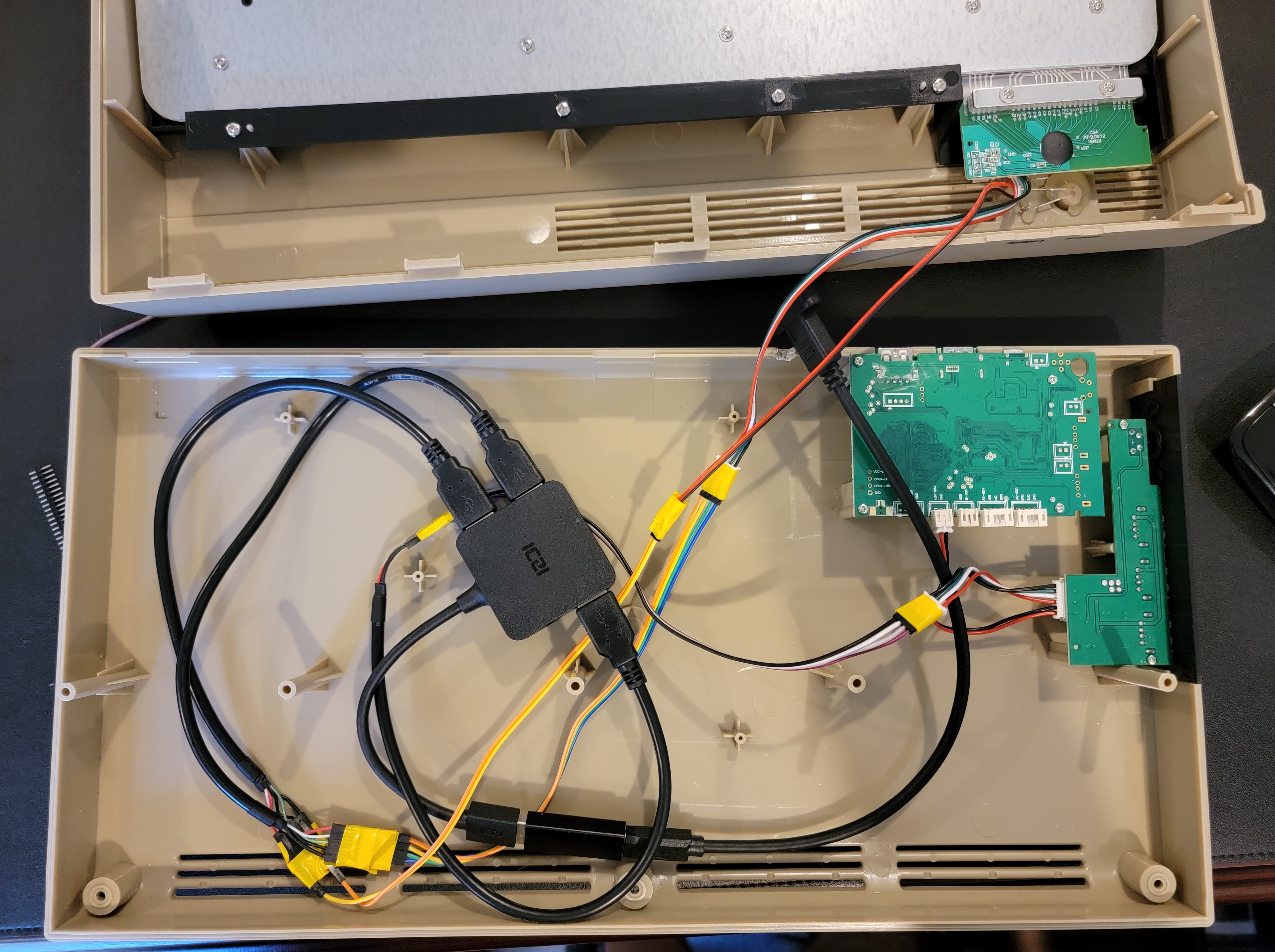
- Connect the USB extension cable to the USB hub.
- Plug the extension cable into a device and test the keyboard, hub, and LED light work properly.
- Route the cable out of the case. I drilled a 1/4 inch hole next to the main board, and I ran the USB extension cable through that opening.
- Close up the case and secure it with the three screws.
Add-ons

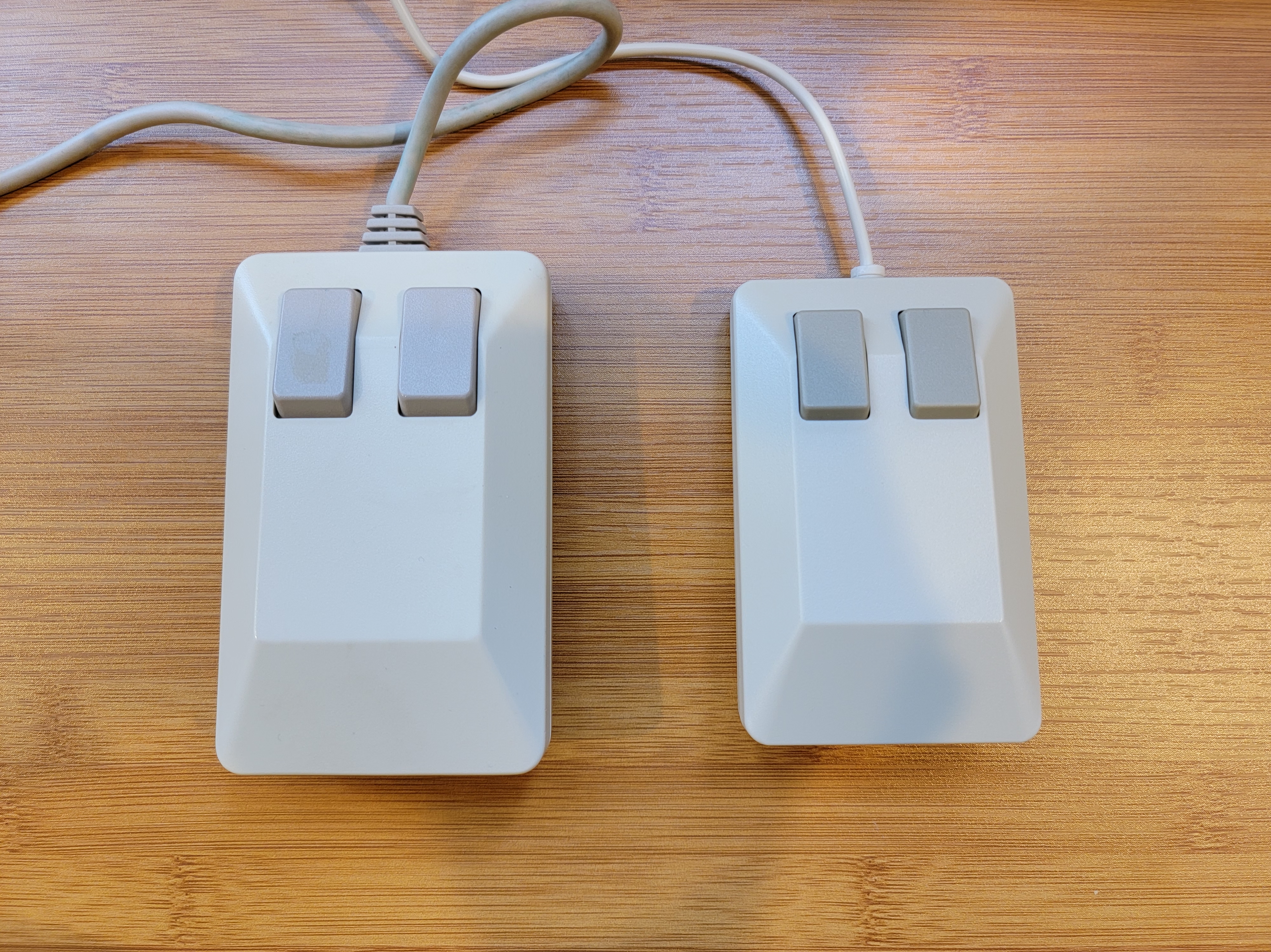

I bought a Retro Games The Mouse to complement the keyboard. That mouse is meant to be an Amiga tank mouse replica for the Retro Games The A500 Amiga replica, but I just pretend it's a Commodore 1351 mouse.
I covered the The C64 badge with a Commodore 64 badge that I found on eBay.
Links
- I'm really excited for the upcoming Commodore 64 crowdfunded relaunch from My Retro Computer.
- Christoph Bartneck retrofitted The C64 with a Raspberry Pi, and it's a wonderful build to watch -- Raspberry C64 Pi Computer
- I used The 8-Bit Guy's Full sized C64 review and disassembly video to plan this mod before I bought The C64 or any of the parts.